Architecture
Frames
This section describes the differnt coordinate systems used. There are two special marker, map and center. map is the origin of the global frame (0,0), center has the property to be seen by all cameras. Every camera has its own frame, as do the center and map.
The coordinate systems (frames) used can be seen in this illustration. The four cameras are depicted by C0 to C3 and are connected via the center marker. C0 can see the marker which represents the origin. When a marker is now seen in C1, C2 or C3, the position in the map frame can be computed by going C0->center->map . The arrow have to be read like a->b means a is parent of b.
For dealing with the different coordinate systems, tf2 is used, the de facto standard transform library for ROS. In the current setup, map and center have to be seen at all time. If they are moved, then the coordinate system changes because the relation between them changes. But as long as they adhere to their position requirements, the package runs. As the transformations obtained by ArUco are from camera to marker, some have to be inversed to get the above graph.
Cameras
We use four ceiling mounted Logitech USB cameras. They are interfaced with the usb_cam package and launched by a custom launch file launch/usb_cam_by_id.xml . They have to have overlapping field of view, at least one marker, the center, has to be seen by all four cameras. For accurate results, the cameras have to be calibrated.
Right now, the cameras are not mounted to a fixed device address, i.e. camera IDs can change when restarting the computer. Therefore, make sure that usb_cam0 is the one which can see the origin marker.
Marker
The marker used are from ArUco and detected by vanilla ar_sys. We use a slightly changed multi_board version launch file (see launch/aruco_multi.xml). The list of boards which can be detected is in config/boards.yml. The origin and center marker HAVE to be called map and center respectively. Other marker have to be prefixed marker. Each board consists of two configuration files: one in pixel and one in meter. We only need the later. These can be found in config/boards and can be generated. To add a new board, either do the way of ArUco and use the command line tools directly or use the scripts in this package. More on that in Scripts.

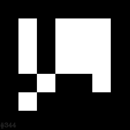
A typical ArUco marker. Each marker encodes a number.
A good overview on ArUco marker can be found in this OpenCV ArUco tutorial or directly on the authors homepage.
Nodes
The following section describes which nodes the panopticon package uses to get the marker positions.
usb_cam
We have one usb_cam node for every camera used. These publish the raw image on /usb_cam$(camera_id)/transform. They are started with the usb_cam_by_id launchfile.
ar_sys
We have one ar_sys multi-board node for every camera. These publish the transformation from camera to marker for each detected marker on cam$(camera_id)/transform. These are started with the aruco_multi launchfile.
panopticon_transformer
This node takes the transformations from the four ar_sys nodes and creates the transformation graph depicted in Frames . That is done by filtering markers and inversing some of the transformations. Marker filtering is necessary, as tf only allows one parent, but a marker can be seen potentially in four cameras, so could have four parents.
panopticon_poser
This node takes the transformations for vanilla markers (not center or map) from the four ar_sys nodes, computes the pose in the world frame and publishes them. As every marker can potentially be seen by four cameras, each marker used has four accompanying topics.
Subscribed topics
The following section lists the topics subscribed and published. These are only the topics of this very package. Topics from ar_sys and usb_cam are omitted, see their respective documentations.
camera0/transform(geometry_msgs/TransformStamped)- The transform from the first camera to each detected marker.
camera1/transform(geometry_msgs/TransformStamped)- The transform from the second camera to each detected marker.
camera2/transform(geometry_msgs/TransformStamped)- The transform from the third camera to each detected marker.
camera3/transform(geometry_msgs/TransformStamped)- The transform from the fourth camera to each detected marker.
Published topics
For every marker listed in the board configuration file that is also detected, panopticon publishes the raw position in world coordinate for every camera. As every marker can potentially be seen by four cameras, each marker used has four accompanying topics.
pose/marker$(markerId)/cam0(geometry_msgs/PoseWithCovarianceStamped)- The pose of marker $(markerId) detected by cam0 in world coordinates.
pose/marker$(markerId)/cam1(geometry_msgs/PoseWithCovarianceStamped)- The pose of marker $(markerId) detected by cam1 in world coordinates.
pose/marker$(markerId)/cam2(geometry_msgs/PoseWithCovarianceStamped)- The pose of marker $(markerId) detected by cam2 in world coordinates.
pose/marker$(markerId)/cam3(geometry_msgs/PoseWithCovarianceStamped)- The pose of marker $(markerId) detected by cam3 in world coordinates.